
Views: 0 Author: Site Editor Publish Time: 2026-08-17 Origin: Site
Thermal inconsistency remains the primary cause of fabric degradation, prolonged drying cycles, and energy waste in commercial garment care. QA engineers, product developers, and facility managers face a distinct challenge. They must verify that a static drying appliance delivers consistent heat distribution across all internal zones. This verification must happen without relying on the mechanical tumbling action found in a standard clothes dryer. Temperature uniformity testing serves as the definitive evaluation framework. It validates cabinet performance, ensures regulatory compliance, and mitigates the risk of product failure or fabric damage. You will learn how to establish success criteria, execute rigorous testing methodologies, and interpret thermal data to optimize appliance design.
Temperature uniformity directly dictates the operational efficiency and fabric safety profile of any static drying appliance.
Standardized multi-point thermocouple testing is required to accurately map thermal gradients and identify cold spots within a clothes drying cabinet.
Evaluating a cabinet against a traditional clothes dryer requires distinct success criteria, prioritizing spatial airflow dynamics over mechanical agitation.
Rigorous environmental isolation—accounting for seasonal ambient extremes—and variable load-state testing are critical to generating reliable, actionable thermal data.
Temperature uniformity defines the performance baseline for any static drying system. Engineers measure it as the temperature delta (ΔT) between the hottest and coldest points within an enclosed space during a steady-state operation. High ΔT values indicate poor airflow and uneven heat distribution. This directly impacts moisture evaporation rates. Water requires consistent thermal energy to overcome its latent heat of vaporization and transition from a liquid to a vapor state. When a cabinet fails to deliver uniform heat, the vapor pressure deficit drops in cooler zones, causing evaporation to stall entirely.
Fabric integrity heavily depends on controlled, predictable heat exposure. Localized thermal spikes pose severe biochemical and structural risks to textiles. Protein fibers, such as wool and silk, denature when exposed to excessive heat. The molecular bonds break down, causing irreversible shrinkage, brittleness, and loss of tensile strength. Synthetic materials like polyester and nylon face different risks. They can glaze, warp, or melt if placed too close to a poorly regulated heating element or an unbaffled hot air inlet. Uniformity testing ensures no single zone exceeds the safe thermal threshold for these specific material classes.
Energy efficiency and cycle times also rely entirely on thermal consistency. Cold spots force the appliance to run longer to dry the entire load. Extended cycle times lead to unnecessary energy consumption. The heating elements, relays, and circulation fans must operate well past their optimal duty cycles. This accelerated wear degrades internal components, particularly PTC (Positive Temperature Coefficient) heaters, and shortens the overall lifespan of the appliance. Achieving a low ΔT guarantees that electrical energy converts efficiently into uniform convective heat, drying garments evenly without wasting power on extended runtimes.
Understanding how different appliances manage heat transfer is necessary for setting accurate testing baselines. Each form factor utilizes distinct thermodynamic principles to remove moisture from textiles.
A traditional clothes dryer utilizes a rotating drum to tumble garments through a high-velocity heated airstream. This mechanical action constantly shifts the load. It exposes different surface areas of the fabric to a concentrated heat source. The tumbling effect naturally compensates for uneven heat distribution within the drum cavity. The constant motion prevents any single garment from resting in a potential cold spot for too long.
However, this method presents distinct limitations. Mechanical agitation causes physical wear on textiles. Fibers break down over time, generating lint and degrading the garment's structural integrity. Furthermore, the core-to-surface temperature of dense items often remains highly inconsistent. The outside of a heavy towel may reach 70°C, while the core remains damp and cool. The reliance on motion masks underlying thermal inefficiencies in the actual airflow design.
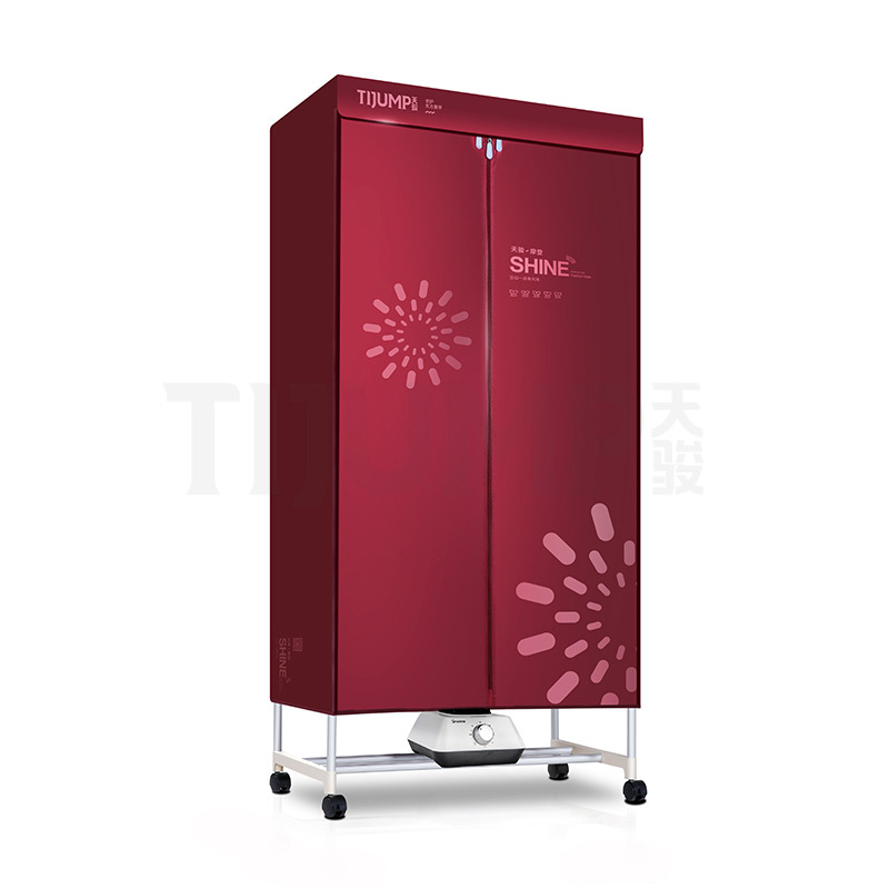
A clothes drying cabinet operates on entirely different thermodynamic principles. It relies strictly on forced air circulation and spatial design to achieve moisture removal without any mechanical agitation. Garments hang statically on racks or hangers. The system must push heated air evenly across the entire internal volume of the enclosure.
The primary engineering challenge lies in fluid dynamics. Fans and baffles must direct uniform heat from the top or bottom elements to the furthest corners of the cabinet. Air naturally takes the path of least resistance. Without careful calibration and aerodynamic baffling, heated air will bypass dense garments and exit directly through the exhaust vent. This short-cycling leaves moisture trapped in the hanging clothes. Testing must verify that convective currents penetrate all designated drying zones, maintaining a high vapor pressure deficit across the entire load.
Scaling down technology introduces severe thermal constraints. A portable clothes dryer operates with a significantly smaller internal volume. The proximity of the heating element to the garments increases the risk of localized heat damage. Thermal mapping in these units often reveals sharp, aggressive temperature gradients. Engineers must design aggressive baffling to diffuse the heat before it contacts the fabric, ensuring the ΔT remains within safe limits despite the cramped geometry.
Similar challenges plague the design of a travelling clothes dryer. These ultra-compact units suffer from inherent airflow bottlenecks. The intake and exhaust vents are often undersized to maintain a small footprint. This restricts volumetric airflow (CFM), causing heat to pool dangerously near the source. Testing establishes a baseline for minimum acceptable performance, ensuring these compact units dry clothes safely without melting delicate travel garments or triggering thermal overload switches prematurely.
Airflow and Heat Transfer Comparison
Appliance Type | Primary Heat Transfer Method | Mechanical Agitation | Airflow Path Complexity | Primary Thermal Challenge |
|---|---|---|---|---|
Tumble Drum | Convection & Conduction | High (Continuous) | Low (Direct through drum) | Core-to-surface temperature variance |
Static Cabinet | Convection | None | High (Requires complex baffling) | Eliminating spatial cold spots |
Compact/Portable | Convection & Radiation | None | Medium (Restricted volume) | Preventing localized heat spikes |
Appliance testing requires strict adherence to established regulatory and testing standards. Protocols from organizations like the IEC (International Electrotechnical Commission, specifically IEC 61121) and AHAM (Association of Home Appliance Manufacturers, HLD-1) govern thermal safety and performance. These frameworks dictate exactly how temperature data should be collected, filtered, and analyzed to ensure repeatability across different testing laboratories.
Commercial and residential certifications require different baselines. Residential units prioritize fabric safety, low noise, and energy efficiency. Commercial units, often used for heavy workwear or turnout gear, prioritize rapid moisture removal and component durability under continuous operation. Certification demands documented proof that the appliance maintains safe operating temperatures under various load conditions. Failure to meet these standards prevents market entry and exposes manufacturers to significant liability.
The core metric of uniformity testing is the maximum allowable temperature variance (ΔT). This is the difference between the hottest and coldest zones within the cabinet during a steady-state cycle. A lower ΔT indicates superior airflow design and better fan calibration. Target deltas shift based on the intended fabric care profile of the appliance.
Delicate silks and synthetics require tight thermal control. A variance of more than ±3°C can cause localized damage or trigger unwanted phase changes in synthetic polymers. Heavy workwear, such as insulated canvas jackets or fire-retardant gear, tolerates higher temperatures. However, testing must ensure the heat penetrates dense fibers without overheating the ambient zones. For these heavy-duty applications, a ΔT of ±5°C to ±7°C is often acceptable, provided the maximum absolute temperature remains below the fabric's degradation point.
Thermal Variance Acceptability Standards
Fabric Category | Target Max Temperature | Acceptable Variance (ΔT) | Primary Thermal Risk |
|---|---|---|---|
Delicates (Silk, Lace) | 40°C - 45°C | ±2°C to ±3°C | Fiber denaturation, shrinking |
Synthetics (Polyester, Nylon) | 50°C - 55°C | ±3°C to ±4°C | Glazing, structural warping |
Standard Cottons | 60°C - 65°C | ±4°C to ±5°C | Over-drying, stiffness |
Heavy Workwear (Canvas, Denim) | 70°C - 75°C | ±5°C to ±7°C | Surface scorching, core dampness |
Determine the target market and primary fabric use-case for the appliance.
Select the corresponding IEC or AHAM testing protocol.
Establish the maximum allowable absolute temperature for the internal cavity.
Define the acceptable ΔT based on the fabric category table above.
Configure the data acquisition system to flag any sensor reading that exceeds these parameters.
Accurate thermal mapping requires precise, repeatable sensor placement. QA engineers utilize Type T (Copper-Constantan) or Type K (Chromel-Alumel) thermocouples arranged in a strict geometric grid. Type T is often preferred for its higher accuracy in the standard drying temperature range (ambient to 100°C). These sensors span multiple horizontal and vertical planes within the cabinet. A standard setup for a full-sized unit includes a 3x3x3 grid, yielding 27 distinct measurement points.
Mapping must cover all critical airflow zones. Engineers place sensors at the air intake to measure source temperature and at the exhaust to monitor heat retention and moisture extraction. Crucially, thermocouples must occupy known dead zones. These include the bottom corners, the spaces directly behind door seals, and the areas immediately beneath hanging rods. Identifying temperature drops in these dead zones highlights airflow deficiencies. Wires must be suspended using high-temperature Kapton tape or non-conductive jigs to prevent thermal bridging with metal racks, which would skew the ambient air readings.
Testing begins with a no-load baseline. Engineers run the empty cabinet through a complete cycle. This establishes the native thermal gradient and airflow efficiency. Without physical obstructions, the data reveals the raw performance of the fans and heating elements. It highlights inherent design flaws, such as asymmetrical fan discharge or poorly sealed seams, before variables are introduced.
Next, engineers execute standard saturated load testing. They introduce standardized wet loads based on AHAM specifications. The process involves weighing bone-dry standard cotton cloths, soaking them, and spinning them in a centrifuge to achieve a precise moisture retention level (typically 50% to 60% of the bone-dry weight). This measures how baseline moisture evaporation alters temperature uniformity. The phase change of water absorbs massive amounts of heat, naturally cooling the surrounding air. The system's PID controller must compensate for this thermal draw without overshooting.
Finally, high-density garment testing pushes the appliance to its limits. Engineers use heavy, dense garments like thick workwear or multi-layered winter coats. These items severely obstruct physical airflow and retain massive amounts of moisture deep within their cores. This stress test evaluates how the internal airflow routes around severe blockages. It ensures the thermal distribution remains stable even when the cabinet is packed to maximum capacity, preventing the unit from short-cycling.
Capturing thermal data requires robust hardware. Thermocouples connect to multi-channel data acquisition (DAQ) systems equipped with cold junction compensation. These devices record temperature fluctuations continuously throughout the drying cycle. A standard sampling rate is one reading per second (1 Hz). This granularity captures rapid temperature spikes or relay chatter that slower sampling rates might miss.
Specialized software visualizes this data in real-time. Engineers watch thermal maps evolve as the cycle progresses. They track the initial heating curve, the steady-state plateau where evaporation occurs, and the final cool-down phase. Real-time monitoring allows technicians to abort tests immediately if temperatures exceed safe thresholds, preventing damage to the prototype or the testing facility.
Raw data holds no value without rigorous analysis. Engineers use the thermal mapping results to locate areas of inadequate circulation. A consistent temperature drop in a specific corner indicates a cold spot. This data directly correlates with physical design elements and internal geometry.
Cold spots often point to specific design flaws. Baffle placement might be directing air away from the side walls. Fan calibration might lack the static pressure needed to push air through dense, wet loads. Exhaust routing might be creating negative pressure zones that siphon heat prematurely before it interacts with the garments. By linking thermal data to physical geometry, engineers can iterate on the design, adjust louver angles, and eliminate bottlenecks.
Temperature uniformity depends entirely on the responsiveness of internal sensors. The cabinet's built-in thermistors (NTC or PTC) feed data to the main control board to regulate the heating elements. QA testing evaluates whether these sensors are calibrated correctly and positioned in the optimal airflow path. They must trigger the heating elements at precise thresholds.
If the elements stay on too long, the cabinet overshoots the target temperature, risking fabric damage. If they shut off too early, the cabinet fails to maintain the necessary heat for evaporation. The hysteresis loop—the lag between sensor reading and element activation—must be tightly controlled via PID tuning. Thermal mapping verifies that the appliance maintains a steady state without aggressive, damaging temperature swings.
Appliance performance must endure over time. Temperature uniformity testing extends to longitudinal degradation analysis, often called accelerated life testing (ALT). Engineers establish parameters to test how the heating elements and fans hold up after 1,000 or more simulated drying cycles.
Over time, PTC heaters can lose efficiency due to thermal cycling fatigue. Fan motors accumulate dust, degrading their bearings and losing RPMs. Door seals compress and harden, allowing hot air to escape and cold ambient air to infiltrate. Longitudinal testing maps the thermal gradient of an aged unit against a brand-new prototype. If the ΔT widens significantly after 1,000 cycles, the components require upgrading to ensure long-term reliability and warranty compliance.
Inaccurate data derails the entire engineering process. Degraded thermocouples or improper spatial positioning introduce massive errors into the DAQ system. If a sensor touches a metal rack instead of measuring ambient air, the reading will spike due to conduction. This false data leads to incorrect design adjustments and wasted prototyping budgets.
Mitigation requires strict laboratory protocols. Mandate pre-test calibration of all thermocouples against a known NIST-traceable standard, often using a dry block calibrator or a precision ice bath. Utilize fixed-jig sensor mounts made from low-thermal-conductivity materials like PTFE. These jigs ensure repeatable placement across multiple test runs. When sensors are locked into exact X, Y, and Z coordinates, the resulting data remains consistent and reliable.
Ambient room conditions heavily skew internal performance data. An appliance draws in surrounding air to heat and circulate. Dry summer intake air requires less energy to heat and holds more moisture than cold, high-humidity winter air. Testing a cabinet on an open factory floor introduces uncontrollable environmental variables that invalidate the test results.
To mitigate this, all uniformity testing must occur within a psychrometric environmental chamber. This isolates the appliance from external thermal fluctuations. Engineers can standardize the intake air baseline, typically setting it to 20°C and 50% relative humidity. They can also simulate extreme environments, from humid coastal climates to arid high-altitude conditions. Chamber isolation guarantees that the thermal data reflects the appliance's actual performance, not the weather outside the facility.
Download the standardized 27-point thermocouple placement schematic to ensure consistent spatial mapping across all static drying enclosures.
Audit your current data acquisition hardware to verify it supports 1 Hz sampling rates with active cold junction compensation.
Schedule a calibration review for all Type K and Type T sensors against a NIST-traceable reference standard before beginning the next prototyping phase.
Upgrade your environmental testing chamber controls to maintain strict intake air humidity and temperature baselines during all load tests.
A: Engineers use multi-point thermocouple grids connected to data acquisition systems. These sensors map thermal gradients across different spatial zones during a cycle. By recording temperatures at the intake, exhaust, and various internal points, they calculate the variance (ΔT) to identify cold spots and heat spikes.
A: Cabinets rely entirely on forced air and convection without mechanical tumbling. In a tumbling drum, clothes move through the heat. In a static cabinet, the heat must move evenly through the stationary clothes. This requires stricter spatial airflow analysis to prevent cold spots and ensure uniform evaporation.
A: Delicate fabrics require tighter tolerances, typically ±2°C to ±3°C, to prevent localized heat spikes that cause shrinking or melting. Heavy workwear testing focuses on penetrating dense fibers without overheating ambient zones, allowing for a broader acceptable variance of ±5°C to ±7°C.
A: Testing must account for the humidity and temperature of the intake air. Dry conditions yield different evaporation rates than damp, cold environments. Psychrometric chambers are necessary for accurate QA because they isolate the appliance from these external fluctuations, ensuring repeatable baseline data.
A: Physical garments obstruct internal airflow and introduce significant moisture. The phase change of evaporating water absorbs heat, creating cooler zones. Testing with standardized wet loads ensures the fans and heaters can overcome these physical and thermal obstacles without short-cycling.
A: The primary culprits include poorly tuned PID controllers causing temperature overshoots, inadequate fan static pressure failing to push air through dense loads, uninsulated door seals leaking heat, and poorly designed exhaust venting that creates airflow bottlenecks.


